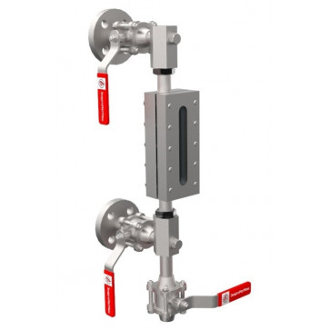
Liquid level indicator (frames No. 2 - No. 9) art.16.113
The pointer is made to order (7-10 working days)
Wafer distance: 320 - 540 mm
Working temperature , no more: 200 °С
Working pressure, no more than: 13 bar
| Наименование | Краткая информация | Артикул | Price | Qty | Add to Cart |
|---|---|---|---|---|---|
| Liquid level indicator (frame No. 2) art.16.113-2 |
The pointer is made to order (7-10 working days) |
16.113-2 |
₴1.00
|
||
| Liquid level indicator (frame No. 3) art.16.113-3 |
The pointer is made to order (7-10 working days) |
16.113-3 |
₴1.00
|
||
| Liquid level indicator (frame No. 4) art.16.113-4 |
The pointer is made to order (7-10 working days) |
16.113-4 |
₴1.00
|
||
| Liquid level indicator (frame No. 5) art.16.113-5 |
The pointer is made to order (7-10 working days) |
16.113-5 |
₴1.00
|
||
| Liquid level indicator (frame No. 6) art.16.113-6 |
The pointer is made to order (7-10 working days) |
16.113-6 |
₴1.00
|
||
| Liquid level indicator (frame No. 7) art.16.113-7 |
The pointer is made to order (7-10 working days) |
16.113-7 |
₴1.00
|
||
| Liquid level indicator (frame No. 8) art.16.113-8 |
The pointer is made to order (7-10 working days) |
16.113-8 |
₴1.00
|
||
| Liquid level indicator (frame No. 9) art.16.113-9 |
The pointer is made to order (7-10 working days) |
16.113-9 |
₴1.00
|
Liquid level indicator with welded stopcocks (frames No. 2 - No. 9) art.16.113
Level indicators art.16.113 have proven themselves well on steam boilers:
- DE series;
- DKVR series ;
- KE series ;
- Viessmann;
- Buderus;
Also, level indicators art.16.113 are installed on other steam boilers, condensate tanks and water storage tanks.
Characteristics
Center distance between flanges: from 320 to 540 mm.
Working medium - water, water vapor, condensate with pH = 9.5 - 10.5.
Working temperature, no more than - 200 °C .
Nominal pressure: 16 bar
Working pressure, no more than: 13 bar
materials
| pos. no. | the name of detail | Qty | Material |
| one | Flange Du20, Ru16 | 2 | Steel 3 |
| 2 | Stainless steel ball valve art.2011 | 3 | Stainless steel |
| 3 | Locking device housing | one | Steel 09G2S |
| four | Sealing ring | four | Graphite |
| 5 | clamp nut | 2 | Steel 09G2S |
| 6 | Level indicator frame art.25.117 | one | Steel 09G2S |
| 7 | Corrugated glass with paronite gaskets | one | Glass / paronite |
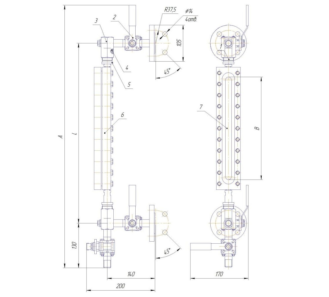
Drawing of the level indicator art.16.113 |
Connecting and overall dimensions of level indicators art.16.113
| Frame No. | Glass size, mm | L,mm* | Ah, mm | V, mm | C, mm ** | D,mm | Weight, kg |
| 2 | 140*34*17 | 320 | 580 | 117 |
105 |
37.5 | 7.9 |
| 3 | 160*34*17 | 360 | 620 | 137 | 8.6 | ||
| four | 190*34*17 | 390 | 650 | 167 | 9.2 | ||
| 5 | 220*34*17 | 420 | 680 | 197 | 9.8 | ||
| 6 | 250*34*17 | 455 | 715 | 227 | 10.5 | ||
| 7 | 280*34*17 | 490 | 750 | 257 | 11.0 | ||
| eight | 320*34*17 | 520 | 780 | 297 | 11.4 | ||
| 9 | 340*34*17 | 540 | 800 | 317 | 12.0 |
* - interaxal dimension L can be changed when ordering.
** - the size of the connecting flange 105mm can be changed when ordering.
Attention! When ordering a level indicator, you must specify its full designation:
Level gauge with threaded stopcocks art.16.113-No.-L-** , where:
1) Level indicator with welded shut-off valves - product name;
2) Art.16.113 - article number of the product;
3) № - index frame number;
4) L - distance between the axes of the connecting flanges in millimeters;
5) ** - the size of the connecting flange is indicated if its size differs from the standard one (105 mm).
If possible, the operating medium, pressure and temperature should also be specified.


